Tesla Model 3: Compressor (Remove and Replace)
Compressor- Remove

Warning:
Only technicians who have been trained in High Voltage Awareness are
permitted to perform this procedure. Proper personal protective equipment (PPE)
and insulating HV gloves with a minimum rating of class 0 (1000V) must be worn
at all times a high voltage cable, busbar, or fitting is handled. Refer to Tech
Note TN-15-92-003, "High Voltage Awareness Care Points" for additional safety
information.
Remove
- Remove the underhood storage unit. See
Underhood Storage Unit (Remove and Replace).
- Remove the outer HVAC plenum duct. See
Duct - HVAC Plenum - Outer (Remove and Replace).
- Recover the A/C refrigerant. See
A/C Refrigerant (Recovery and Recharge).
Note: Recover the refrigerant while continuing this procedure.
- Disconnect 12V power. See
12V Power (Disconnect and Connect).
- Perform the vehicle electrical isolation procedure. See
Vehicle Electrical Isolation Procedure.
- Remove the penthouse HV cap. See
Cap - Penthouse HV (Remove and Replace).
- Remove the LH 2nd row seat side bolster. See
Bolster - Side - Seat - 2nd Row - LH (Remove and Replace).
- Remove the LH rear sill panel trim. See
Trim - Sill Panel - Rear - LH (Remove and Replace).
.png)
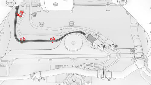
- Release the clips that attach the low voltage electrical harness to the
charge port to HV battery harness bracket at the penthouse.
.jpg)
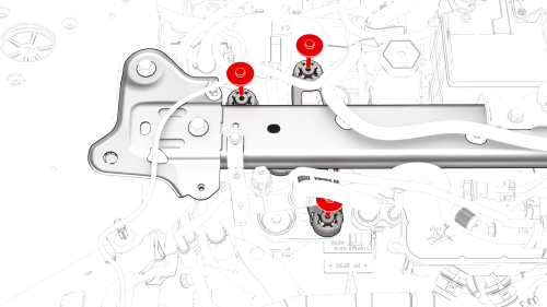
- Remove the bolts that attach the charge port to HV battery harness
bracket at the penthouse, and then remove the bracket from the vehicle.
.jpg)
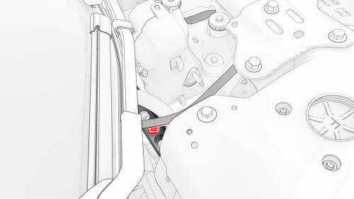
- Release the clip that attaches the charge port electrical harness to the
vehicle.
.jpg)
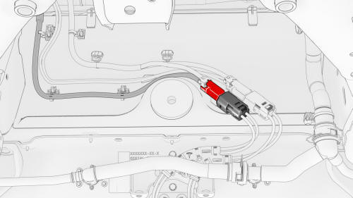
- Slide the security tab to the unlock position, release the locking
handle, and then disconnect the charge port electrical harness from the
penthouse DC input connector.
- Remove the front aero shield. See
Panel - Aero Shield - Front (Remove and Replace).
- Disconnect the compressor HV electrical connector from the HV electrical
harness.
- Release the clips that attach the compressor HV electrical harness to
the bulkhead.
.jpg)
- Disconnect the electrical harness from the high pressure transducer
connector.
- Lower the vehicle.
.png)
- Disconnect the low voltage electrical connector from the compressor.
.jpg)
- Remove the bolt that attaches the ground harness to the compressor.
.png) Torque 6 Nm
Torque 6 Nm
- Release the clips that attach the low voltage electrical harness to the
compressor and compressor bracket.
.png)
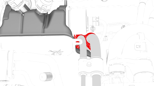
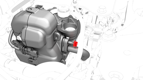
- Remove the bolt that attaches the suction/liquid line bracket to the
shock tower brace, and then separate the bracket from the brace.
.png)
- Disconnect the electrical harness from the low pressure transducer
connector.
Note: Make sure that the refrigerant has fully recovered before
continuing this procedure.
.png)
- Remove the bolt that attaches the suction/liquid line to the chiller and
EXV assembly, and then remove the line from the chiller and EXV assembly.
- Remove and discard the o-rings from the suction/liquid line fitting.
.png)
- Release the clip that attaches the electrical harness to the suction
liquid line.
.png)
- Disconnect the electrical harness from the powertrain coolant pump
connector.
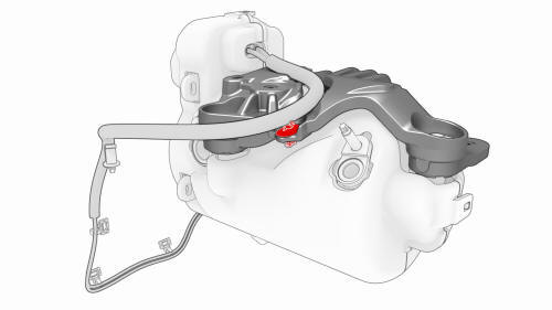
- Release the clip that attaches the suction/liquid lines to the
superbottle.
.png)
- Remove the nut that attaches the discharge line to the compressor, and
then remove the discharge line from the compressor.
- Remove and discard the o-ring from the discharge line.
- Remove the nut that attaches the suction/liquid line to the compressor,
and then remove the suction/liquid line from the compressor.
- Remove and discard the o-ring from the suction/liquid line.
- Release the clip that attaches the compressor HV electrical harness to
the crossbeam.
- Move the compressor HV electrical harness forward of the shock tower
brace to ease compressor removal.
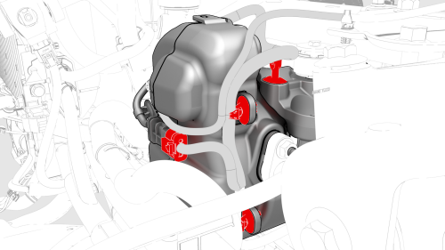
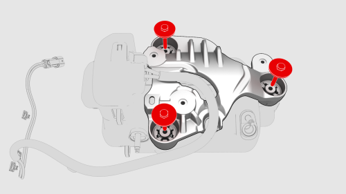
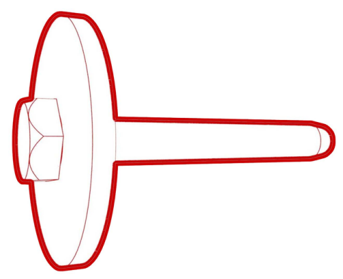
- Remove the bolts that attach the compressor to the shock tower brace,
and then lower the compressor and remove it from the vehicle.
Caution:
Set the compressor so that the refrigerant fittings are up, and oil
will not leak from them. Before the replacement compressor can be installed, the
removed compressor and the oil inside must be weighed.

- Release the clip that attaches the compressor HV electrical harness to
the intermediate bracket.
- Remove the bolts that attach the intermediate bracket to the compressor,
and then remove the bracket from the compressor.
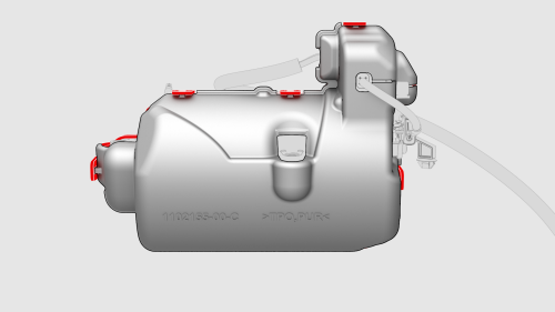
- Release the clips that attach the acoustic cover over to the compressor,
and then remove the acoustic cover.
- Use a digital scale to weigh the removed compressor and record its
weight.
Note: Do not drain any oil from the removed compressor.
Compressor- Install
- Remove the port plugs and port nuts from the replacement compressor.
- Use the digital scale to weigh the replacement compressor and record its
weight.
- Subtract the weight of the removed compressor from the weight of the
replacement compressor. The difference is the weight of oil to be removed
from the replacement compressor.
- Turn the replacement compressor upside down to drain a small amount of
oil from the suction (large) port into a clean, dry collection container.
Note: If necessary, the collected oil can be reused later
for A/C system recharge.
- Repeat step
2 through step
4 until the weight of the replacement compressor is the same as the
removed compressor.
- Install the acoustic cover over the compressor, and then fasten the
clips that attach the cover over the compressor.
- Install the intermediate bracket onto the compressor, and then install
the bolts that attach the bracket to the compressor.
 Torque 10 Nm
- Fasten the clip that attaches the compressor HV electrical harness to
the intermediate bracket.
- Install the compressor under the shock tower brace, and then install the
bolts that attach the compressor to the shock tower brace.
Torque 10 Nm
- Move the compressor HV electrical harness behind the shock tower brace.
- Fasten the clip that attaches the compressor HV electrical harness to
the body.
- Install a new o-ring onto the suction/liquid line, insert the line into
the compressor, and then install the nut that attaches the line to the
compressor.
 Torque 22 Nm
- Install a new o-ring onto the discharge line, insert the line into the
compressor, and then install the nut that attaches the line to the
compressor.
Torque 22 Nm
- Fasten the clip that attaches the suction/liquid lines to the
superbottle.
- Connect the electrical harness to the powertrain coolant pump connector.
- Fasten the clip that attaches the electrical harness to the suction
liquid line.
- Install new o-rings onto the suction/liquid line fitting, install the
fitting into the chiller and EXV assembly, and then install the bolt that
attaches the fitting to the chiller and EXV assembly.
.png) Torque 5.5 Nm
Torque 5.5 Nm
- Connect the electrical harness to the low pressure transducer connector.
- Install the suction/liquid line bracket onto the shock tower brace, and
then install the bolt that attaches the bracket to the brace.
.png) Torque 5.5 Nm
Torque 5.5 Nm
- Fasten the clips that attach the low voltage electrical harness to the
compressor and compressor bracket.
- Install the bolt that attaches the ground harness to the compressor.
Torque 6 Nm
- Connect the low voltage electrical harness to the compressor connector.
- Raise the vehicle.
- Connect the electrical harness to the high pressure transducer connector.
- Fasten the clips that attach the compressor HV electrical harness to the
bulkhead.
- Connect the compressor HV electrical connector to the HV electrical
harness.
- Install the front aero shield. See
Panel - Aero Shield - Front (Remove and Replace).
- Connect the red high pressure hose to the vehicle's high pressure port,
and the blue low pressure hose to the vehicle's low pressure port.
- Start the A/C vacuum and leak test, and continue with this procedure
while the tests are running.
- Perform the penthouse air leak test. See
Penthouse Air Leak Test.
- Connect the charge port electrical harness to the penthouse DC input
connector. Close the locking handle and slide the security tab to the lock
position.
- Install the clip that attaches the charge port electrical harness to the
vehicle.
.jpg)
- Position the charge port to HV battery harness bracket on the body, and
then install the bolts that attach the bracket to the body.
.jpg) Torque 10 Nm
Torque 10 Nm
- Install the clips that attach the low voltage electrical harness to the
charge port to HV battery harness bracket at the penthouse.
- Install the LH rear sill panel trim. See
Trim - Sill Panel - Rear - LH (Remove and Replace).
- Install the LH 2nd row seat side bolster. See
Bolster - Side - Seat - 2nd Row - LH (Remove and Replace).
- Install the penthouse HV cap. See
Cap - Penthouse HV (Remove and Replace).
- Connect 12V power. See
12V Power (Disconnect and Connect).
Note: Do not install the rear apron at this time.
- When the A/C vacuum and leak test is complete, recharge the refrigerant.
See
A/C Refrigerant (Recovery and Recharge).
- Connect a laptop with Toolbox to the vehicle.
- Update the vehicle firmware.
- After the A/C refrigerant recharge has fully completed, verify the
operation of the A/C system.
- Connect a charge cable to the vehicle, and then use Toolbox to run the
"TEST-SELF_VCFRONT_X_THERMAL-PERFORMANCE" test to verify the replacement
compressor operation.
- Disconnect the charge cable and laptop from the vehicle.
- Install the outer HVAC plenum duct. See
Duct - HVAC Plenum - Outer (Remove and Replace).
- Install the underhood storage unit. See
Underhood Storage Unit (Remove and Replace).
READ NEXT:
Remove
Remove the cooling fan module. See
Module - Cooling Fan (Remove and Install).
Release the clips (x14) that attach the active grille shutter to the
cooling fan module, and then rem
SEE MORE:
Panel - Door Trim - Front - LH (Remove and Install) - Remove
Remove
Open the front LH door, and fully lower the window.
Remove the front LH door tweeter. See
Tweeter - Front Door - LH (Remove and Replace).
Remove the LH front door puddle light. See
Puddle Light - Front Door - LH (Remov
Overview
The Calendar app allows you to view
scheduled events from your phone's (iPhone
or Android) calendar for the current and next
day. The Calendar is conveniently integrated
with navigation and the Phone app so you can
navigate to, or dial into, your next meeting.
The Calendar app requ
 Condenser (Remove and Replace)
