Tesla Model 3: HV Header - Inverter - Rear Drive Unit (Remove and Replace)
SPECIAL TOOLS
Extractor, Drive Unit HV Header, Model 3
(1142608-00-B)
Lever Lock, HV Connector, Model 3 (1140311-00-A)
Only technicians who have been trained in High
Voltage Awareness are permitted to perform this
procedure. Proper personal protective equipment (PPE)
and insulating HV gloves with a minimum rating of
class 0 (1000V) must be worn at all times a high
voltage cable, busbar, or fitting is handled. Refer to Tech
Note TN-15-92-003, "High Voltage Awareness Care Points" for
additional safety information.
Remove
Install
Note: Push, pull, and push on the header to make
sure it is fully seated.
Caution:
Make sure that the harness fits the connector
squarely and tightly.
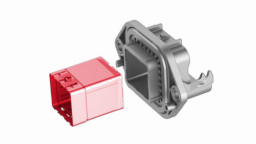
HV Header - Inverter - Rear Drive Unit - Remove
.jpg)
.png)
.jpg)
.png)
.png)
.png)


HV Header - Inverter - Rear Drive Unit - Install
.png) Torque 6 Nm
Torque 6 Nm
.png)
.png) Torque 6 Nm
Torque 6 Nm
READ NEXT:
 Inverter Air Leak Test
DRAFT
Warning: This procedure was derived from pre-production computer
models, and might not reflect the real-world situation. Warnings
and cautio
SEE MORE:
Brake Fluid Bleed / Flush
SPECIAL TOOLS
Brake System Servicing Equipment (1054715-01-A)
Flare nut crowfoot set (1079041-00-A)
Adapter, Brake Bleeder, PowerProbe T
Garnish - Trunk (Remove and Replace)
Remove
LH shown, RH similar
Open the trunk.
Release the clips (x2) that attach the ends of the trunk garnish to the
body.
Release the tabs (x10) that attach the trunk garnish to the body, and
then remove the trunk garnish from the vehicle.
Install
Installation procedure is the
