Tesla Model 3: Passthrough - DCDC - 12V (Remove and Replace)
SPECIAL TOOLS Skt, 1/4in Dr, 5-Lobe Torx Plus External (1059330-00-B) Resistance meter, microohm, Hioki RM 3548 (1076927-00-A) Remove
Install
Install the nut that attaches the negative terminal of the DCDC harness to
the negative DCDC passthrough busbar, and then mark the nut with a paint pen
after it is torqued.
Note: The maximum acceptable resistance is 0.100 mΩ (100 μΩ). If
the resistance is above this value, escalate a Toolbox session, as appropriate.
Note: The maximum acceptable resistance is 0.100 mΩ (100 μΩ). If
the resistance is above this value, escalate a Toolbox session, as appropriate.Passthrough - DCDC - 12V- Remove

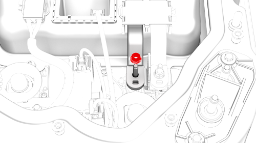


.png) Torque 15 Nm
Torque 15 Nm
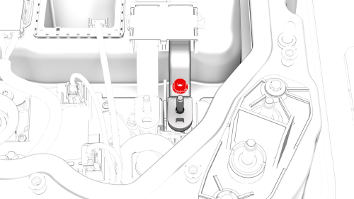
Passthrough - DCDC - 12V- Install
 Torque 10 Nm
 Torque 20 Nm
Torque 15 Nm
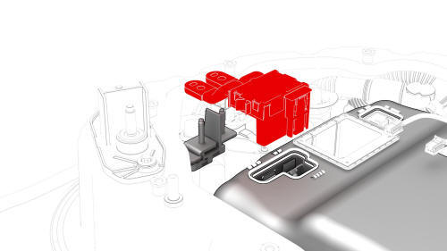
.jpg) Torque 4.5 Nm
Torque 4.5 Nm
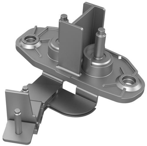
Torque 4.5 Nm.jpg) Generic Measurement - Actual busbars and fasteners might appear
different
Generic Measurement - Actual busbars and fasteners might appear
different
Generic Measurement - Actual busbars and fasteners might appear
different
READ NEXT:
 Power Conversion System (Remove and Replace)
Power Conversion System- Remove
SPECIAL TOOLS
Connector Removal, Coolant, PCS, M3 (1111868-00-B)
Kit, Svc Plug, Cooling Hose, Model 3 (1135762-00-A)
Tool, Vacuum Cup, 3" x 6" (Qty 2) (1114917-00-A)
SEE MORE:
Inverter Coolant Leak Test
DRAFT
Warning:
This procedure was derived from pre-production computer
models, and might not reflect the real-world situation. Warnings
and cautions might be missing. Follow safety requirements and
use extreme caution when working on or near high voltage s
Carpet - Front - LH (Remove and Replace)
DRAFT
Warning:
This procedure was derived from pre-production computer models, and
might not reflect the real-world situation. Warnings and cautions might be
missing. Follow safety requirements and use extreme caution when working on or
near high voltage systems and components.
Do not redistribu
